Calibrating a Real Time Clock in Tympan
Share
In talking with users of the Tympan, data logging is something that they'd like the Tympan to do. Furthermore, for the data logging to be useful, the data needs to be time stamped. So, the Tympan needs to know the time and date. Normally, one needs to add a dedicated real-time clock (RTC) circuit for a device to know the time and date. Luckily, the Teensy 3.6 that is at the heart of the Tympan has most of the required elements already built in. Let's finish it off to make it work!
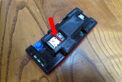 |
| My Tympan with the RTC mod. The red wire is the only indication that it has been modified. |
Use our LiPo Battery Instead of a Coin Cell. For Tympan, I don't want to try to squeeze a coin cell battery into the Tympan's enclosure. We already have a perfectly good battery in the system (the LiPo battery that powers the whole device). Can't we use that battery for the RTC, too? I think that we can.
Providing Power, Even When "Off". There are two tricks to using the LiPo battery. First, we need to bring the LiPo power to the RTC circuit on the Teensy even when the Tympan's power switch is set to "off". In other words, we have to be choosy about where we grab the LiPo power when we bring it to the RTC. Second, before we connect the LiPo to the RTC, we need to step down the LiPo voltage (3.7-4.2V) so that it won't damage the RTC (< 3.6V).
 |
| The red arrows show the many choices for where to grap the LiPo power for the Teensy's RTC. I chose to grab the LiPo power from the Fuse F1, as shown by the heavy red arrow. |
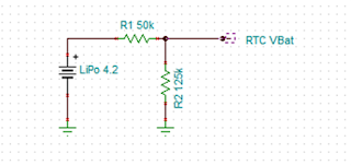
Stepping Down the Voltage. After choosing place to grab the LiPo power, we need to step down its voltage to a safe level. One can use a variety of techniques. Since the current draw for the RTC is very, very low (about a microamp?), I chose to use a simple voltage divider.
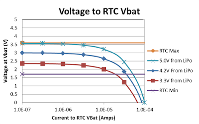
Designing the Voltage Divider. According to the datasheet for the Teensy' microprocessor, the voltage at the RTC battery pin needs to be between 1.71V and 3.6V. We need to step down the LiPo voltage to say within these bounds. To decide what resistor values to use, I am going to assume that the LiPo can go down to 3.3V and maybe as high as 5V (which would only happen if I were to make a wiring mistake while hacking). Given these limits, I chose to use a 50K resistor (high side) and a 125K resistor (low side). As can be seen in the graph below, these resistor values mean that the voltage will be good for any RTC current draw up to 10-50 microamps. Looks great!
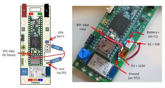
Wire it Up. Given this voltage divider design, the picture below shows what I did. I chose to grab the LiPo voltage by soldering the 50K resistor to side of the fuse F1. I chose to grab ground by soldering the 125K resistor to TP2 (which is ground). The RTC VBat is taken from the midpoint between the two resistors. I soldered a short red wire from the mid point up to the hole on the Teensy for the RTC VBat. Because these modifications are so small, the modified Tympan fit back into its enclosure without any issues (as shown in the photo at the top of this post).
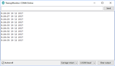
Testing the RTC. To test the real time clock, I used one of the Teensy example programs. The RTC example programs are part of the "Time" library that comes with the Teensysduino installer. If you didn't install the Time library, go back and re-install Teensyduino and you should be good. The specific example program that I used was "TimeTeensy3". I made no modifications to the program. It compiled and uploaded to the Tympan without any issues.
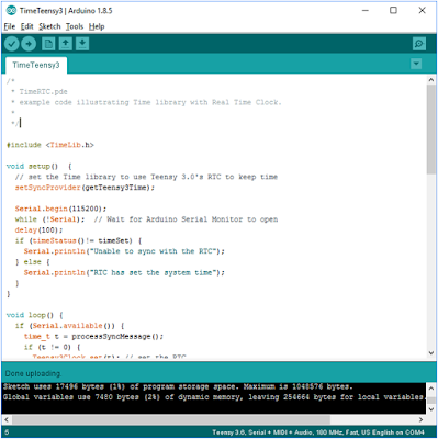 |
| To test the RTC on the Tympan, I used the "TimeTeensy3" example program that was made for the Teensy. |
Losing RTC Power, The only problem with this setup is if the RTC counter loses power. In my case, this would happen if the LiPo becomes fully drained. When the RTC counter loses power, it loses its count. When power is restored, the RTC will start counting again from zero. The reference time, however, will not have been reset. So, when we ask the RTC what time it is, it'll use the original reference time and we'll get the wrong answer. So, if the LiPo becomes fully discharged, you'll want to reset the RTC by recompiling and re-uploading the program, or by looking at the Time library to figure out how to manually set the time.
Overall, I was impressed at how easy it was to get the RTC working on this system. A couple of resistors and a piece of wire? Easy! Now that the Tympan knows the time and date, it'll be much more useful as data logging device. For future users of Tympan, I'm looking forward to incorporating this modification. But, for those of you with the current version of Tympan (Rev C), you'll have to get out the soldering iron. Maybe you're like me and find that to be a fun thing to do!

